Leibniz 101: a simple guide to Xaoc Devices’ binary subsystem
Table of Contents
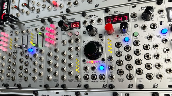
Eurorack boffins Xaoc Devices recently released Berlin, a digital oscillator with a difference. It’s part of their Leibniz binary subsystem: a family of digital modules that can create and share 8-bit signals using a special rear-panel connector. Depending on how you combine the various modules, you can create unique sound processors, CV signal manipulators, wavetable oscillators, generative sequencers, rhythm machines and much more - all based around 8-bit data.
But how exactly does the Leibniz binary subsystem work, what are the modules in the range, how do you set it up and - most importantly - how can you use it to make music? Whether you’re curious about Leibniz but aren’t sure where to start, or you’ve already got some modules but need some inspiration, this article - and our accompanying video - will demystify the subsystem and offer some practical patching examples.
What is the Leibniz binary subsystem?
 Portrait of Leibniz, 1695
The ‘Leibniz’ part is a reference to Gottfried Wilhelm Leibniz, the 17th-century German mathematician and philosopher who, among many other things, refined the binary number system that forms the basis of pretty much all computer science. Xaoc Devices refer to it as a ‘subsystem’ because the modules can communicate via their own special bus using 10-pin ribbon cables.
As for the ‘binary’ part: well, the basic concept behind the subsystem is that an analogue audio or CV signal can be represented by an 8-bit digital signal - essentially a stream of binary numbers that define the voltage at any given moment. You can perform various operations on the bits, like inverting, swapping, looping, re-clocking or otherwise changing them in ways that don’t have obvious equivalents in the analogue domain. And at lower frequencies, the changing states of the individual bits can be used to derive trigger or gate patterns.
 Diagram from the Drezno II manual showing the gate patterns produced by an 8-bit representation of a saw wave
It’s worth emphasising that there’s nothing special about the digital signals in the Leibniz binary subsystem. Although they can be transmitted between modules using 10-pin ribbon cables for convenience, the signals are simply parallel streams of 5V gates - one for each of the eight bits. The gates are either high or low (on or off) depending on whether the bit that they represent is a one or a zero. If a particular Leibniz module provides access to the bits via standard Eurorack jacks on the front panels, you can treat them in the same way as any other signal in your system.
A quick note on binary numbers
If you’re already fluent in binary, skip ahead to the next section, but if you’re new to the concept or need a refresher, here’s a quick explanation.
The standard number system we’re all familiar with is called decimal, or base 10, and we probably ended up using it because we have 10 fingers. We count up in units from 0 to 9, then start a new column to record the tens. Once we’ve counted up to 99 - i.e. 9 tens plus 9 ones - we add a new column on the left to keep track of the hundreds. When we reach 999, we start a new column to keep track of the thousands, and so on. The columns represent powers of 10: 100 is 1, 101 is 10, 102 is 100, and so on.
Binary, or base 2, works on the same principle, but instead of using 10 digits (0 to 9), it uses only two: 0 and 1. This means when we’ve counted 0 and 1, we add a new column on the left to keep track of the twos. Once we’ve counted up to three, which is ‘11’ in binary - 1 two plus 1 one - we need to start a new column to keep track of the fours. And we keep adding columns in the same way, but the columns represent powers of 2, rather than 10. This means the value represented by the column simply doubles each time: 1, 2, 4, 8, 16, 32, 64, 128, 256, 512 and so on.
Each binary digit is known as a bit, and in an ‘8-bit’ binary number they represent (in left to right order) 128, 64, 32, 16, 8, 4, 2 and 1. This means an 8-bit number can have 256 possible values, ranging from 00000000 to 11111111 and all the possible permutations in between. The left-most digit (representing 128) is known as the ‘most significant bit’ (MSB) and the right-most digit (representing 1) is the ‘least significant bit’ (LSB).
| Example: binary 01011011 | ||||||||
| Binary digit | 0 | 1 | 0 | 1 | 1 | 0 | 1 | 1 |
| Decimal value | 128 | 64 | 32 | 16 | 8 | 4 | 2 | 1 |
| Therefore decimal equivalent = 64 + 16 + 8 + 2 + 1 = 91 | ||||||||
How does the Leibniz binary subsystem work?
A good place to see the theory put into practice is the Drezno II module, which serves as the input/output front end in a typical Leibniz setup. It has two halves: an analogue-to-digital converter (ADC) on the left and a digital-to-analogue converter (DAC) on the right. You feed an analogue signal - audio or CV - into the left side to convert it to digital data. You can then send that data through other modules in the Leibniz subsystem using the 10-pin connector on the rear, or you can access the individual streams of bits via the front panel jacks.
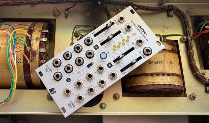
Once your digital data has been processed in some way, you can convert it back to analogue via the right side of Drezno II. There’s a 10-pin connector on the rear that accepts a stream of data via the Leibniz bus, or you can patch bits in manually on the front panel.
One quick way of processing the signal quite drastically using Drezno II alone is to connect the ADC output directly to the DAC input via the Leibniz bus at the rear, then use the front panel jacks to manually override and swap bits - patch bit 7 out of the ADC to bit 6 in on the DAC, for example. This can result in some pretty extreme waveshaping effects.
Clocking in the Leibniz binary subsystem
You can think of the ADC side of Drezno II as a quantised sample-and-hold. When you feed an analogue signal to the input, on each clock pulse it will ‘sample’ the voltage of that signal at that particular moment The voltage is quantised to one of 256 possible values and ‘held’ as an 8-bit binary number (with the eight gates set to either 5V or 0V depending on whether their corresponding bit is a 1 or a 0) until the next clock pulse.
 A diagram from the Drezno II manual illustrating the ADC process
Drezno II has a 2MHz internal clock, which means by default it carries out this sampling process 2 million times a second! But you can replace this clock with your own via the ADC clock input, and this clock can be as fast, slow or irregular as you like, so you can use Drezno for sample-rate reduction effects on audio, or to generate rhythmic gate patterns or stepped modulation from slower CV signals. Whichever clock you use, it’s transmitted alongside the eight bits of data on the Leibniz bus.
What modules are in the range?
There are currently eight dedicated Leibniz modules, plus a couple of others in the Xaoc Devices range that offer some degree of Leibniz functionality.
Core Leibniz modules
Drezno II: designed as a way to interface with the rest of your system, providing analogue-to-digital and digital-to-analogue conversion with direct access to the outgoing and incoming bit streams via the front panel. For many Leibniz setups, this is the obvious starting point, and there’s a lot you can do with this unit alone.
XAOC Devices Drezno II Eurorack Leibniz Binary ADC & DAC Module

£265.00
Drezno II is an improved version of the original Drezno module. It is an essential member of the 8-bit Xaoc Devices Leibniz Binary Subsystem. The...… read more
Berlin: a simpler option if you’re most interested in using the Leibniz subsystem for VCO-type applications. It’s a wide-range digital oscillator that includes a DAC and outputs a perfect rising ramp wave on the Leibniz bus that’s ideal for driving Jena, turning the pair into an 80s-style wavetable VCO or LFO.
XAOC Devices Berlin Eurorack Leibniz Oscillator Module

£198.00
On the surface, Xaoc Devices Berlin is a simple compact VCO offering square and saw waves with hard sync, FM input and octave switching.The most...… read more
Jena: the perfect partner for Berlin, Jena contains several banks of transform functions that can turn Berlin’s simple rising saw wave into a host of other complex waveshapes. As well as wavetable oscillator applications, it includes a special bank that generates drum patterns via the individual bit outputs.
XAOC Devices Jena Eurorack Leibniz Binary Transfunctioner Module

£242.00
Jena is a component of the Leibniz Binary Subsystem which operates on signals and voltages through manipulating binary 8-bit numbers. Jena connects to the Drezno...… read more
Erfurt: a binary counter with eight outputs that represent the bits in an 8-bit number. As you add to (or subtract from) the number, using clock signals, the on/off status of the bits change accordingly. You can use it as a clock divider, or pair it with Lipsk to change the count increment and generate complex rhythmic patterns at each bit output.
XAOC Devices Erfurt Eurorack Leibniz Binary Phase Accumulator Module

£145.00
Erfurt is a bi-directional digital counter, frequency divider, and a component of the 8-bit Leibniz Binary Subsystem. It has multiple applications: the output of the...… read more
Lipsk: a relatively simple module that sits on the Leibniz bus and lets you invert the state of each of the eight bits, either with a manual push switch or a gate input, allowing for radical transformation of the 8-bit data. It also pairs well with Erfurt as a way of defining the count increment.
Xaoc Devices Lipsk Eurorack Leibniz Binary Processor Module (V1)

£130.00
Lipsk facilitates the inversion of the individual bits produced by Drezno II (or any other module connected to its input header at the back), and...… read more
Gera: similar to Lipsk, this is a deceptively simple module that acts on Leibniz data passing through it. Individual bit streams can be ‘masked’ (i.e. turned off) via manual push switches or gate inputs, opening up more ways of transforming the 8-bit data, including bit reduction/crushing effects.
XAOC Devices Gera Eurorack Leibniz Binary Processor Module

£147.00
Gera is a component of the Leibniz subsystem that allows masking individual bits of the digital data by the use of logical AND operation. It...… read more
Rostock: a binary data pipeline, or shift register, which lets you delay the data stream by passing it through a ‘pipeline’ of up to 64 stages. You can loop, scramble and reclock the pipeline - at lower clock speeds it’s great for CV looping and mangling, and at higher speeds you can achieve lo-fi digital chorus and flanging effects.
XAOC Devices Rostock Eurorack Leibniz Binary Data Pipeline Module

£230.00
Rostock is a component of the Leibniz Binary Subsystem. It is a data pipeline, a FIFO (first in-first out) shift register, or a very short...… read more
Poczdam: a routing module for the Leibniz subsystem that lets you switch between two Leibniz sources, reclock the data and access the bitstreams via the front panel. It also has an independent, CV-controllable clock source with a very wide range of speeds, which is handy when you’re getting into advanced Leibniz patches.
XAOC Devices Poczdam Eurorack Leibniz Binary Data Router Module

£198.00
Poczdam is a binary data routing solution for the Xaoc Devices Leibniz subsystem. It allows manual and remote switching between two Leibniz data sources, modifying...… read more
Other Xaoc modules with Leibniz functionality
Ostankino II: the expander for Moskwa II, Xaoc’s 8-step sequencer, provides an 8-bit representation of the voltage value set by each step. A bus connector lets you pipe this data into other Leibniz modules, or you can access the individual bits via jacks on the panel.
Odessa: the digital additive oscillator has a Leibniz bus input which lets you turn banks of partials on or off according to the status of the bits. This can produce subtle timbral changes driven by other parts of your patch.
Some simple Leibniz combinations & patch examples
The Leibniz subsystem is so open-ended that it can feel pretty daunting, but the key to getting your head around things is to focus on one simple application at a time - you don’t need to connect everything to everything.
A good place to start is by choosing two modules and exploring the possibilities of that pairing before expanding. If you end up with a lot of Leibniz modules, it may be better to configure them as multiple ‘sub-subsystems’ for specific purposes rather than trying to combine everything into one. Here are a few suggested configurations and starting points. And remember to check out our video that walks through some of these patch ideas.
Drezno II + Gera/Lipsk/Rostock
For straightforward processing of audio or CV signals, Drezno II is the obvious place to start. Before you try connecting any other modules, simply connect the LBZ OUT of Drezno II to the LBZ IN on the rear panel (make sure everything is powered off and double-check your ribbon cable orientation when you do this!) and activate the LINK button on the front of Drezno.
Feed a simple wave from a VCO into the ADC input. Set the gain about halfway and set the offset to max on the ADC side. Set the gain to max and offset to zero on the DAC side, with the range switch set to High. Listen to the DAC out - the input signal should be largely unchanged other than a subtle quantising effect as a result of being converted to 8-bit and back. Then try the following:
Manually cross-patch some bits on the front panel of Drezno II - for example, swap bits 5 and 6 - and listen to how it affects the sound.
Patch a high audio-frequency clock, like a square wave from another VCO or the dedicated clock output of Poczdam, to the ADC clock input and play with the frequency to explore sample rate reduction effects. Try running the same pitch sequence to both VCOs and play with the tuning of the clocking oscillator to move between harmonic and inharmonic ratios.
Try patching one of the bit outputs from the ADC side to the DAC clock input for more complex sample rate reduction effects
If you have Gera or Lipsk, power it down and insert it into the LBZ chain. (Connect the LBZ OUT of Drezno II to the LBZ IN of Gera/Lipsk, and connect Gera/Lipsk’s LBZ OUT back to the LBZ IN on Drezno II to complete the chain.) Experiment with activating and deactivating the switches and listen to the effect they have on the sound. Try patching rhythmic patterns from a sequencer to the gate inputs to dynamically alter the sound. Try switching using audio-rate signals for more drastic effects!
If you have Rostock, connect it into the Leibniz loop as above, then try feeding an LFO into Drezno. Clock the ADC at a multiple of the LFO rate to get a repeating stepped modulation shape, then experiment with the Loop button on Rostock to capture sections of it. Try hitting Scramble to randomise it. Then experiment with similar effects on audio-rate signals. NB: when processing audio, you’ll need to clock the ADC at a suitably slow rate for Rostock’s buffer length to have an audible effect.
Berlin + Jena
If you’re interested in exploring VCO applications, this simple pairing offers instant gratification. Simply connect the LBZ OUT of Berlin to the LBZ IN on Jena, and the LBZ OUT of Jena back to the LBZ In on Berlin. Set Jena to asynchronous mode (‘E OFF’), then try the following:
Send a pitch sequence to the V/oct input on Berlin and engage the LBZ LINK switch to listen to the wave produced by Jena. Browse through the various banks and shapes on Jena using the encoder. Patch a modulation source like an LFO or envelope to the Shape CV input and scan through the shapes for classic wavetable-style patches.
Select a simple wave shape in Jena, such as the sine in bank 7, shape 000. Patch a sine wave from a separate VCO to the Phase input on Jena to experiment with through-zero phase modulation. Use an attenuator or VCA to vary the strength of the modulating wave and control the depth of modulation. Notice how, unlike in conventional FM, the pitch of the main oscillator isn’t affected when using PM.
Switch Berlin to the LO frequency range and select bank 15 in Jena. Use the individual bit outputs from the front panel of Jena to trigger drum sounds, and scan through the shapes to listen to the various drum patterns. To synchronise it to the rest of your patch, use the Pitch knob on Berlin to adjust the BPM and send a regular reset signal (derived from your master clock) to the hard sync input.
Erfurt + Lipsk
For exploring rhythmic gate patterns and clock/frequency dividing, this pairing is surprisingly powerful. It’s the simplest possible Leibniz configuration: just connect the LBZ out of Lipsk to the LBZ in of Erfurt. Lipsk allows you to define a binary number, using the buttons and gate inputs, which determines the increment of the count whenever Erfurt gets a clock at the INCR or DECR inputs. For example, with only the bottom button activated on Lipsk, the increment will be 1, so Erfurt will simply count up (or down) one number at a time. Start with this, then try the following:
Feed a steady clock signal into the INCR input on Erfurt and notice the pattern at the bit outputs - simply counting up in binary results in the bits changing progressively more slowly, so working from the bottom output upwards, you get clock divisions of /2, /4, /8, /16, /32, /64, /128 and /256.
Patch the bit outputs from Erfurt to trigger drum sounds, then change the count increment on Lipsk and observe how the bit outputs start changing in more complex rhythms. Switch the incoming clock to the DECR input and see how the trigger patterns change again. Generally for rhythm pattern generation, you’ll get more ‘musical’ results using the DECR input (see the Erfurt manual for more detail on this!)
Get even more complex patterns by using one or more bit outputs from Erfurt patched back into one of the bit inputs of Lipsk. This way, when a particular bit is activated, it will change the count increment. You can tame things by regularly resetting Erfurt. As always, experiment to see what sounds cool!
Want to know more?
If you’ve got questions about the Leibniz binary subsystem then don’t hesitate to drop us an email. Tom’s produced several videos on his channel that go into some of the combinations in more detail - you can watch these below. Keep an eye on Xaoc Devices’ YouTube channel and Instagram feed too for even more patch ideas!
